图书介绍
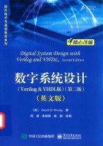
数字系统设计 Verilog&VHDL版 第2版 英文版PDF|Epub|txt|kindle电子书版本网盘下载

- (美)黄爱基 著
- 出版社: 北京:电子工业出版社
- ISBN:9787121334214
- 出版时间:2018
- 标注页数:406页
- 文件大小:45MB
- 文件页数:422页
- 主题词:硬件描述语言-程序设计-高等学校-教材-英文
PDF下载
下载说明
数字系统设计 Verilog&VHDL版 第2版 英文版PDF格式电子书版下载
下载的文件为RAR压缩包。需要使用解压软件进行解压得到PDF格式图书。建议使用BT下载工具Free Download Manager进行下载,简称FDM(免费,没有广告,支持多平台)。本站资源全部打包为BT种子。所以需要使用专业的BT下载软件进行下载。如BitComet qBittorrent uTorrent等BT下载工具。迅雷目前由于本站不是热门资源。不推荐使用!后期资源热门了。安装了迅雷也可以迅雷进行下载!
(文件页数 要大于 标注页数,上中下等多册电子书除外)
注意:本站所有压缩包均有解压码: 点击下载压缩包解压工具
图书目录
CHAPTER 1 Introduction to Microprocessor Design1
1.1 Overview of Microprocessor Design3
1.2 Design Abstraction Levels6
1.3 Examples of a 2-to-1 Multiplexer7
1.3.1 Behavioral Level7
1.3.2 Gate Level9
1.3.3 Transistor Level11
1.4 Introduction to Hardware Description Language11
1.5 Synthesis15
1.6 Going Forward16
1.7 Problems17
CHAPTER 2 Fundamentals of Digital Circuits18
2.1 Binary Numbers19
2.1.1 Counting in Binary20
2.1.2 Converting between Binary and Decimal20
2.1.3 Octal and Hexadecimal Notations23
2.1.4 Binary Number Arithmetic25
2.2 Negative Numbers27
2.2.1 Two’s Complement Representation27
2.2.2 Sign Extension29
2.2.3 Signed Number Arithmetic30
2.3 Binary Switch32
2.4 Basic Logic Operators and Logic Expressions33
2.5 Logic Gates35
2.6 Truth Tables36
2.7 Boolean Algebra and Boolean Equations38
2.7.1 Boolean Algebra38
2.7.2 Duality Principle41
2.7.3 Boolean Functions and Their Inverses41
2.8 Minterms and Maxterms46
2.8.1 Minterms46
2.8.2 Maxterms49
2.9 Canonical,Standard,and Non-Standard Forms52
2.10 Digital Circuits53
2.11 Designing a Car Security System54
2.12 Verilog and VHDL Code for Digital Circuits57
2.12.1 Verilog Code for a Boolean Function57
2.12.2 VHDL Code for a Boolean Function58
2.13 Problems59
CHAPTER 3 Combinational Circuits65
3.1 Analysis of Combinational Circuits66
3.1.1 Using a Truth Table67
3.1.2 Using a Boolean Function70
3.2 Synthesis of Combinational Circuits72
3.2.1 Using Only NAND Gates75
3.3 Minimization of Combinational Circuits76
3.3.1 Boolean Algebra77
3.3.2 Karnaugh Maps78
3.3.3 Don’t-Cares85
3.3.4 Tabulation Method86
3.4 Timing Hazards and Glitches89
3.4.1 Using Glitches91
3.5 BCD to 7-Segment Decoder92
3.6 Verilog and VHDL Code for Combinational Circuits95
3.6.1 Structural Verilog Code95
3.6.2 Structural VHDL Code97
3.6.3 Dataflow Verilog Code101
3.6.4 Dataflow VHDL Code102
3.6.5 Behavioral Verilog Code103
3.6.6 Behavioral VHDL Code104
3.7 Problems106
CHAPTER 4 Standard Combinational Components112
4.1 Signal Naming Conventions113
4.2 Multiplexer114
4.3 Adder117
4.3.1 Full Adder117
4.3.2 Ripple-Carry Adder118
4.3.3 Carry-Lookahead Adder120
4.4 Subtractor123
4.5 Adder-Subtractor Combination125
4.6 Arithmetic Logic Unit129
4.7 Decoder137
4.8 Tri-State Buffer140
4.9 Comparator142
4.10 Shifter146
4.11 Multiplier149
4.12 Problems151
CHAPTER 5 Sequential Circuits157
5.1 Bistable Element159
5.2 SR Latch160
5.3 Car Security System—Version 2163
5.4 SR Latch with Enable164
5.5 D Latch164
5.6 D Latch with Enable166
5.7 Verilog and VHDL Code for Memory Elements166
5.7.1 VHDL Code for a D Latch with Enable168
5.7.2 Verilog Code for a D Latch with Enable169
5.8 Clock169
5.9 D Flip-Flop171
5.9.1 Alternative Smaller Circuit175
5.10 D Flip-Flop with Enable176
5.10.1 Asynchronous Inputs177
5.11 Description of a Flip-Flop180
5.11.1 Characteristic Table180
5.11.2 Characteristic Equation180
5.11.3 State Diagram180
5.12 Register181
5.13 Register File182
5.14 Memories188
5.14.1 ROM190
5.14.2 RAM192
5.15 Shift Registers197
5.15.1 Serial-to-Parallel Shift Register199
5.15.2 Serial-to-Parallel and Parallel-to-Serial Shift Register200
5.15.3 Linear Feedback Shift Register202
5.16 Counters205
5.16.1 Binary Up Counter205
5.16.2 Binary Up Counter with Parallel Load207
5.17 Timing Issues210
5.18 Problems211
CHAPTER 6 Finite-State Machines215
6.1 Finite-State Machine Models217
6.2 State Diagrams221
6.3 Analysis of Finite-State Machines224
6.3.1 Next-State Equations225
6.3.2 Next-State Table226
6.3.3 Output Equations228
6.3.4 Output Table228
6.3.5 State Diagram229
6.3.6 Example230
6.4 Synthesis of Finite-State Machines234
6.4.1 State Diagram235
6.4.2 Next-State Table236
6.4.3 Next-State Equations237
6.4.4 Output Table and Output Equations237
6.4.5 FSM Circuit238
6.5 Optimizations for FSMs239
6.5.1 State Reduction239
6.5.2 State Encoding240
6.5.3 Unused States243
6.6 FSM Construction Examples243
6.6.1 Car Security System—Version 3243
6.6.2 Modulo-6 UP-Counter245
6.6.3 One-Shot Circuit249
6.6.4 Simple Microprocessor Control Unit251
6.6.5 Elevator Controller Using a Moore FSM254
6.6.6 Elevator Controller Using a Mealy FSM258
6.7 Verilog and VHDL Code for FSM Circuits261
6.7.1 Behavioral Verilog Code for a Moore FSM261
6.7.2 Behavioral Verilog Code for a Mealy FSM265
6.7.3 Behavioral VHDL Code for a Moore FSM266
6.7.4 Behavioral VHDL Code for a Mealy FSM269
6.8 Problems270
CHAPTER 7 Dedicated Microprocessors283
7.1 Need for a Datapath286
7.2 Constructing the Datapath287
7.2.1 Selecting Registers293
7.2.2 Selecting Functional Units294
7.2.3 Data Transfer Methods295
7.2.4 Generating Status Signals297
7.3 Constructing the Control Unit302
7.3.1 Deriving the Control Signals303
7.3.2 Deriving the State Diagram305
7.3.3 Timing Issues312
7.3.4 Deriving the FSM Circuit315
7.4 Constructing the Complete Microprocessor320
7.5 Dedicated Microprocessor Construction Examples323
7.5.1 Greatest Common Divisor323
7.5.2 High-Low Number Guessing Game330
7.5.3 Traffic Light Controller337
7.6 Verilog and VHDL Code for Dedicated Microprocessors341
7.6.1 FSM+D Model342
7.6.2 FSMD Model351
7.6.3 Algorithmic Model354
7.7 Problems356
CHAPTER 8 General-Purpose Microprocessors362
8.1 Overview of the CPU Design363
8.2 The EC-1 General-Purpose Microprocessor365
8.2.1 I nstruction Set365
8.2.2 Datapath366
8.2.3 Control Unit368
8.2.4 Complete Circuit372
8.2.5 Sample Program372
8.2.6 Simulation374
8.2.7 Hardware Implementation374
8.3 The EC-2 General-Purpose Microprocessor375
8.3.1 Instruction Set375
8.3.2 Datapath376
8.3.3 Control Unit378
8.3.4 Complete Circuit383
8.3.5 Sample Program383
8.3.6 Hardware Implementation386
8.4 Extending the EC-2 Instruction Set387
CHAPTER 9 Interfacing Microprocessors390
9.1 Multiplexing 7-Segment LED Display391
9.1.1 Theory of Operation391
9.1.2 Controller Design392
9.2 Issues with Interfacing Switches393
9.3 3×4 Keypad Controller401
9.3.1 Theory of Operation401
9.3.2 Controller Design404